
Residential Home Well Water System Diagram
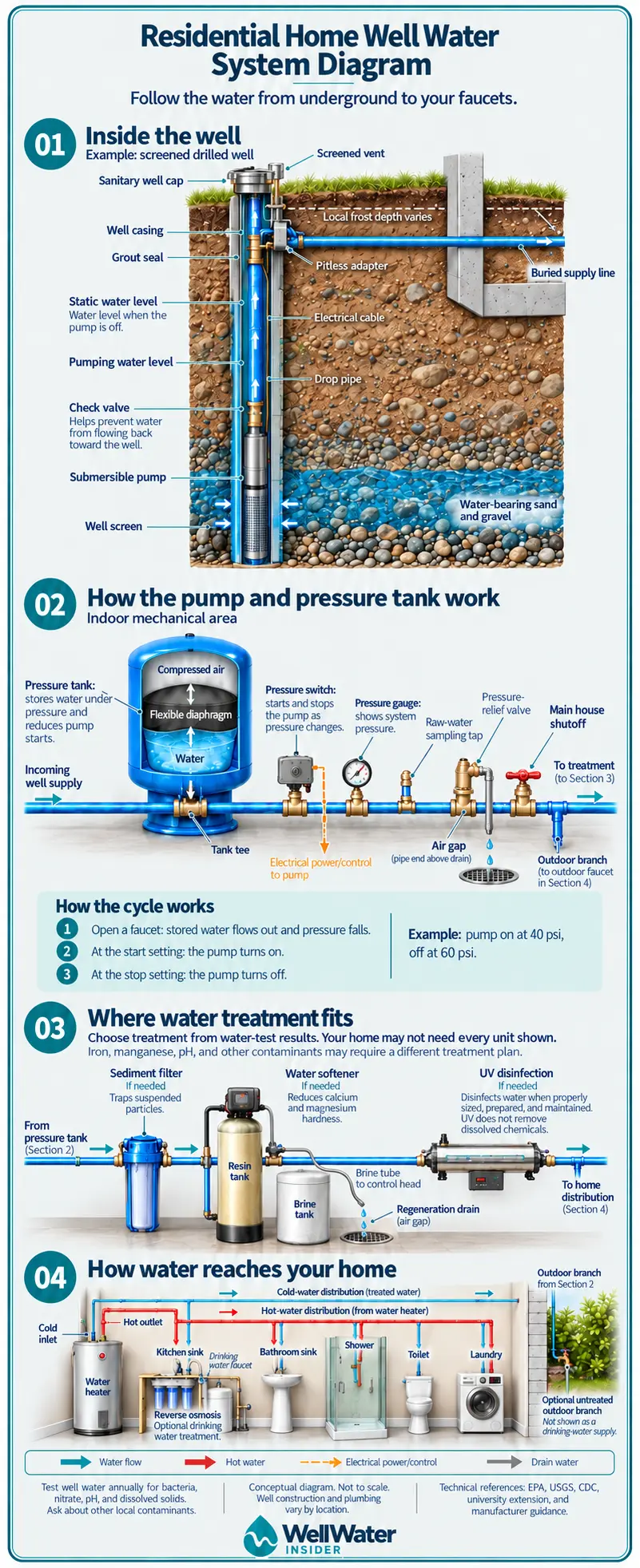
Follow the water from the aquifer to your kitchen faucet. Every part of a home well system, labeled and explained in plain English, and free to share or embed on your own site.
- You needNothing
- Takes6 minute read
- CostFree to share and embed
Share or embed this diagram on your site
Blogs, schools, home inspectors, well drillers and plumbers are welcome to use it. Copy the code, paste it into any page, and the diagram appears with a credit link back to Well Water Insider.
In short: a home well system moves water through four stages. A submersible pump lifts groundwater up the well. A pressure tank and switch store it and keep the pressure steady. Optional treatment cleans up whatever your water test finds. Then the house plumbing splits it into cold and hot lines for every tap. The diagram above follows that path from the aquifer to your kitchen faucet.
How to read this residential home well water system diagram
Most people never see their well system as one piece. The pump is hundreds of feet underground, the tank sits in a basement or utility closet, and the pipes disappear into walls. So when something goes wrong, it is hard to picture what the plumber is talking about.
The residential home well water system diagram fixes that by laying the whole path out in order. Teal arrows show water moving, red arrows show hot water, the dashed orange line is the electrical control for the pump, and gray marks drain water. It is a conceptual drawing, not a construction plan. Your well may be deeper, your tank may sit in a different spot, and your county may require parts this picture leaves out.
Section 1: inside the well
The example in the diagram is a drilled well with a screen at the bottom, the kind you find in sand and gravel aquifers. Here is what each label means, from the top down.
- Sanitary well cap and screened vent. The cap seals the top of the casing so insects, mice and surface water stay out. The vent lets air move in and out as the water level rises and falls.
- Well casing and grout seal. The casing is the steel or plastic pipe that lines the hole. Grout fills the gap between the casing and the earth, which stops surface water from running straight down the outside of the pipe into your water.
- Pitless adapter. This fitting lets the water line leave the casing sideways below the frost line, so the pipe to the house never freezes. Frost depth changes a lot from Georgia to Minnesota, which is why the diagram says it varies.
- Static and pumping water levels. Static level is where the water sits when the pump is off. Pumping level is where it drops to while the pump runs. The gap between the two tells a driller a lot about how well the aquifer keeps up.
- Drop pipe, electrical cable and check valve. The drop pipe carries water up to the pitless adapter, the cable powers the pump, and the check valve keeps water from draining back down when the pump shuts off.
- Submersible pump and well screen. The pump sits near the bottom and pushes water up. The screen lets water in while holding back sand. In a bedrock well there is often no screen at all, and water seeps in through cracks in the rock.
If you want the real numbers for your own well, the driller’s well log lists the depth, casing length and water levels. Our well record finder shows where your state keeps those logs.
Section 2: how the pump and pressure tank work together
The second panel is the part most homeowners can actually touch. Water from the well arrives at a tank tee, and from there it fills the pressure tank. Inside the tank, a flexible diaphragm separates the water from a cushion of compressed air. As water comes in, the air squeezes tighter and the pressure climbs.
The pressure switch watches that pressure and runs the pump. Open a faucet and the tank pushes water out until the pressure falls to the switch’s start setting. The pump kicks on, refills the tank, and shuts off at the stop setting. The diagram uses 40 psi on and 60 psi off as an example. Without the tank, the pump would start every time someone filled a glass, and that constant cycling wears pumps out fast.
Along the same pipe you will usually find a pressure gauge, a raw-water sampling tap and a pressure-relief valve. The sampling tap matters more than it looks. It gives you water straight from the well, before any filter or softener, which is what a lab needs when you want to know what is really in your well. The relief valve drains to a floor drain through an air gap, a short open space that keeps drain water from ever being pulled back into the supply. An outdoor branch often splits off here, before treatment, for hoses and garden spigots.
Section 3: where water treatment fits
The diagram shows three common units in a row: a sediment filter, a water softener and a UV disinfection light. Each one is marked “if needed,” and that is the most important label on the page. Treatment should follow a water test, not a hunch. Plenty of homes need one unit or none at all.
The usual order works like this. A sediment filter goes first and catches sand and grit that would foul everything downstream. A softener comes next and swaps out the calcium and magnesium that cause hard-water scale; it flushes itself on a schedule, so its regeneration drain also gets an air gap. A UV unit usually goes last, because it can only kill bacteria if the water flowing past the lamp is already clear.
UV is also easy to misunderstand. The diagram notes that it does not remove dissolved chemicals, and that is accurate: UV does nothing for nitrate, arsenic or lead. Iron, manganese and acidic water each need their own approach. If you have lab results in hand, our treatment planner checks them against EPA limits and suggests what to install and in what order.
Section 4: how water reaches each tap
After treatment, the water splits. One cold line feeds the toilets, sinks, shower, laundry and the cold inlet of the water heater. The heater sends hot water back out on its own line to the same fixtures.
Two details in this panel are easy to miss. First, a reverse osmosis unit often sits under the kitchen sink as an optional drinking-water filter with its own small faucet. It handles the dissolved contaminants a whole-house system leaves behind. Second, the outdoor branch from Section 2 stays untreated. That saves your softener salt and filters, but it also means the garden hose is not a drinking-water tap.
Using the residential home well water system diagram to troubleshoot
Knowing the order of the parts helps you narrow down a problem before you call anyone.
| What you notice | Where to look first |
|---|---|
| Pump clicks on and off every few seconds | Pressure tank, which may have lost its air charge |
| No water at all | Breaker, pressure switch, then the pump |
| Sand or grit in the water | Well screen or pump setting, then the sediment filter |
| Rotten-egg smell only on hot water | Water heater anode rod, not the well |
| Positive bacteria test | Well cap, casing and grout seal, then shock chlorination |
The bottom of the diagram repeats the advice that keeps the whole system honest: test your well every year for bacteria, nitrate, pH and dissolved solids, as the CDC recommends, and ask a local lab about other contaminants common in your area. Our certified lab finder lists state-certified labs near you. If a test comes back positive for bacteria, the shock chlorination calculator works out the exact bleach dose for your well.
Residential well water system questions
What are the main parts of a home well water system?
The well itself (casing, cap, grout seal and screen), a submersible pump with its drop pipe and check valve, a pitless adapter and buried line to the house, a pressure tank and pressure switch, any treatment equipment your water test calls for, and the cold and hot water plumbing inside the home.
Why does a well need a pressure tank?
The tank stores water under pressure so the pump does not have to start every time a tap opens. That keeps the pressure steady and saves the pump from short cycling, which is one of the most common reasons pumps fail early.
Where should a sampling tap go on a well system?
Before any filter, softener or UV unit, usually right after the pressure tank. Water from that tap shows what is actually coming out of the well, which is what a lab needs to judge your water.
Does every well need water treatment?
No. Treatment should follow a lab test. Many wells need nothing, some need a single unit, and a few need several in a specific order. The diagram marks each treatment unit as “if needed” for exactly that reason.
Can I use this diagram on my own website?
Yes. It is free to share for blogs, schools, contractors and home inspectors. Use the embed code at the top of this page so the diagram stays sharp and keeps the credit link to Well Water Insider.
Conceptual diagram, not to scale. Well construction and plumbing vary by location and local code. Testing advice follows the CDC’s guidelines for private wells; treatment notes follow EPA and university extension guidance.